Sunday, December 11, 2022

Santa Fe's Early 2-10-2s in Victorville, and More Helpers for My Layout

This time we'll look at Santa Fe's early 2-10-2 steam locos that were operating in Victorville in the late 1940s.  Then we'll look at a little more layout progress, thanks to two more helpers who visited me.

Santa Fe's first 2-10-2 steam locos were built in 1903-1904 and were numbered 900-984.  A virtually identical group of 2-10-2s were built in 1905-1907 and were numbered 1600-1673.  In 1912-1913 they got another batch, numbered 1674-1705.

Two more groups were created when they cut apart the unsuccessful 2-10-10-2 locos of the 3000-class into two halves in 1915-1918.  These became numbers 3010-3019 and 3020-3029. 

So, the early 2-10-2 locos we'll look at here are from the 900 class, 1600 class, 1674 class, 3010 class, and 3020 class.

Here we see two locos from the 900 class, #945 and #979, taking water at Keenbrook while uncoupled from the rear of an eastbound freight in June, 1949, thanks to Jack Whitmeyer:


Frank Peterson shot #979 helping bigger 2-10-2 #3833 with a westbound freight near Frost (after leaving Victorville) in 1947:


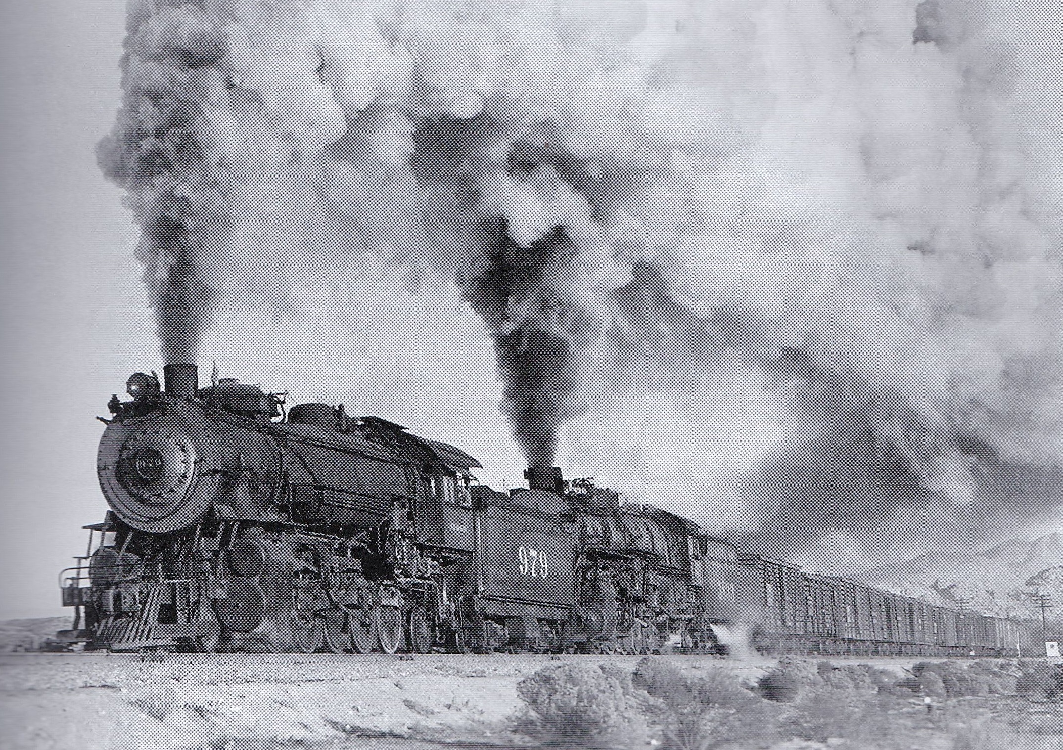
Here we see #1626 and #979 pushing on the rear of an eastbound freight at Pine Lodge in June, 1949, in a nice shot by Stan Kistler:


Herb Sullivan shot #1676 helping a 4-8-4 with an eastbound passenger train approaching Sullivan's Curve in 1946:


In May of 1950, Jack Whitmeyer shot #1677 in the San Bernardino B Yard (all the other shots I've seen of these locos were taken in 1949 or earlier):


Here's an action shot of #1677 with an eastbound freight at Cajon in June, 1949, thanks to Stan Kistler:


Stan Kistler also shot #1689,
freshly shopped at San Bernardino in Feb. 1947:


James Ady shot #3013 and 4-8-2 #3723 pushing an eastbound freight at Devore in August of 1947:


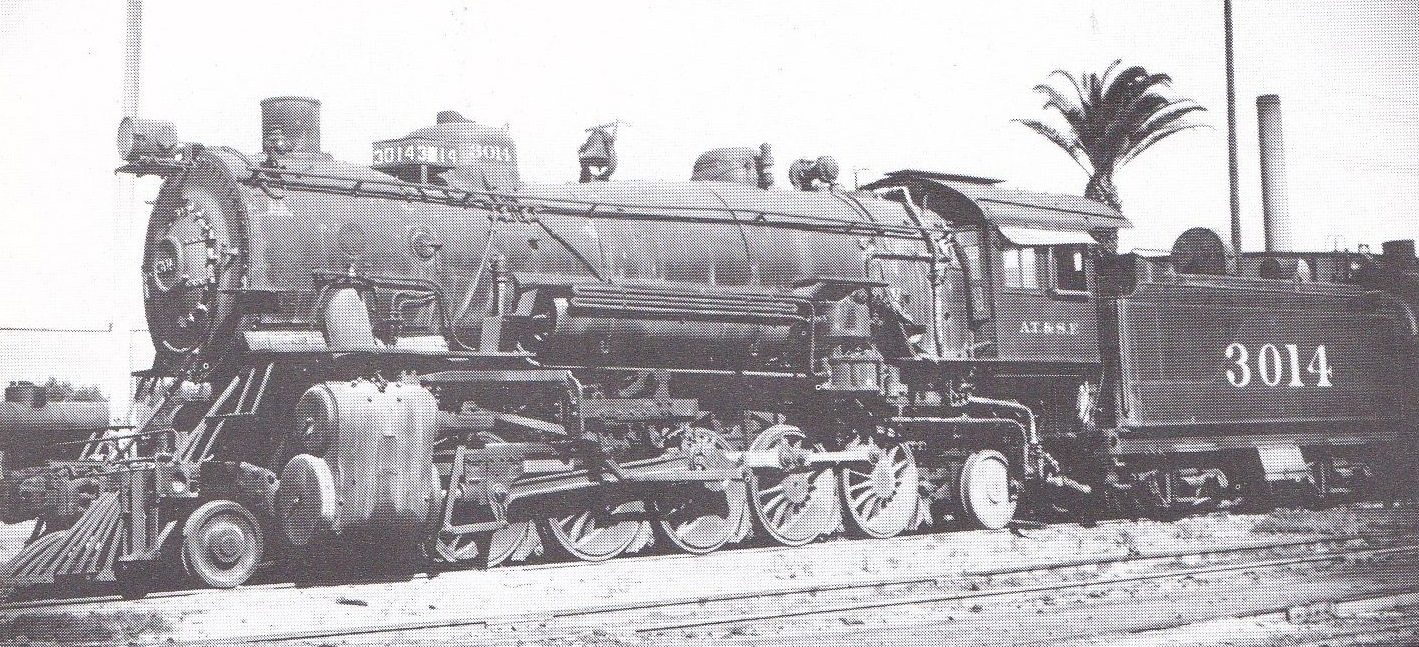
Finally, Tom Baxter shot #3014 at San Bernardino in Nov. 1948:


As we've seen, these locos were normally used as helpers on Cajon Pass in the postwar years, and they were out of action after 1949 or 1950.

There have been various HO brass models of the locos in these similar classes.

Hallmark made a 900-class model, like this one (mine is #979):


Division Point also made a 900 class, but I don't have this model (and this one happens to have a coal tender):


Westside made a 1600 class, as seen here with a turtleback tender (mine is #1690):


Division Point also made a 1600-class loco, which I don't have:


Westside also made a 3010-class loco (mine is not yet painted):


Now it's time for a layout progress update.  I had no visitors the week before last, due to all the snow we got that week.

But I bought some Velcro parts and found a way to make straps to support my bus wires along the edges of the layout.  I bought a roll of 3/4" wide Velcro strap, which I cut into 4" lengths, which are about right for attaching to the benchwork and then rolling into a circle around the bus wires.  I also bought a pack of 7/8" square sticky-back Velcro squares for attaching the straps to the inside of the 1x4" edge boards. 

The edge boards are rough on the back side, so I cut 2" wide clear packing tape into 2" squares to first stick to the inside of the boards, and then the sticky-back Velcro squares are stuck to the smooth tape, and then the Velcro straps are stuck to the Velcro squares and then curled around the bus wires.  The Velcro will open to allow me to add more bus wires into the straps later.
 
This view shows the products being used and four of the Velcro straps around the bus wires, spaced about 12" apart under the edge boards:


Here is a view from under the layout edge, showing the Velcro strap attached to the Velcro sticky-back square, which is stuck to the clear tape on the board:
 

I also did some initial design work for the three mainline control panels, one for each of the three "tower" areas around the layout.  I think I should build and wire these mainline panels before dealing with the separate yard panels:

The large circles are the rotary switches to assign cabs to blocks, and the small vertical ovals are the toggles for the powered switch machines (I added an X beside those that control both turnouts in a crossover).  Each switch toggle will also need a momentary pushbutton beside it, but I didn't yet draw those in.  The short lines through the tracks are the block boundaries (a double line marks the end of a reversing section).

My wiring advisors, Tim Fisher and Richard Mukai, reviewed this drawing and got back to me with some improvements I need to make when I find time.  We're also discussing what electrical parts I need to buy for these panels.

This week I had two helpers visit me -- Ray Rydberg on Wednesday afternoon, and then Bill Messecar on Thursday morning.

I had never met Ray before, but he's about my age and is planning to build a new HO layout to replace an unfinished one from years ago.  He brought along his rough track plan, which we agreed to discuss and develop in the coming weeks.

Ray got the job of cutting and stripping lots of feeder wires for all the sections of track along the outer mainline.  The holes were already drilled beside the rails, so he inserted each wire he cut to reach to the nearest suitcase connector on the bus wires.  Here's a posed photo of Ray hard at work (on his knees):


While Ray was working for almost four hours, I was adding more masking tape to lift the bus wires and their connectors into the right locations for Ray.

Then my old friend Bill Messecar arrived the next morning, and he went to work soldering most of the feeder wires to the rails.  He was very good and very fast at this, and he even fixed some of the botched soldering jobs I had done.  I forgot to shoot a photo of Bill at work, but I'll do it next time, when he returns to finish the last parts of the outer mainline.

While Bill was soldering, I was adding more Velcro straps to hold the bus wires around part of the layout, but  there are still quite a few more to add.  I've also begun to clamp the suitcase connectors to the soldered feeder wires, as seen in this photo of me on my knees:


Progress will slow down now, with Christmas just two weeks away.  I'll back with another blog entry in three weeks.  Happy Holidays!


Sunday, November 27, 2022

UP's PA Diesels in Victorville, and Finding Volunteers to Help Build My Layout

Our featured locomotives this time are the Alco PA-1 and PB-1 diesels of the Union Pacific.  My layout progress report will be about recruiting volunteers to help build my layout, including the first visit by one of my volunteers.

The UP acquired three PA-PB-PA sets in Sep. 1947, with leading cab numbers of 994A-997A.  These were soon renumbered to 600-603 in March, 1948.  Then in Jan. 1949 they acquired four PA-PB sets with leading cab numbers of 604-607.

Chard Walker shot a three-unit PA set entering Victorville through the Upper Narrows, passing the Rainbow Bridge, with an eastbound secondary passenger train in the late 1940s (beautiful):


In October, 1947, before the renumbering into the 600-series, set #997 with the eastbound Utahn was climbing near Alray, thanks to the Richard Kindig Collection:


The UP mixed their PA and PB units together as needed.  Here is a PA-PB-PB set #602 passing the Victorville Lime Rock plant with a westbound passenger train in 1953, as shot by Don Sims from up on the Rainbow Bridge approach (I love this shot!):


Here we see a PA-PB-F3 set with a heavyweight train, being helped eastbound up Cajon Pass by 4-8-2 #7019, as shot by Chard Walker:


The PAs were also mixed with FM Erie-Built units, as seen here at Summit with the eastbound LA Limited in June, 1952, as shot by Robert Hale.  The UP TR5 cow-calf set on the right helped the train to Summit:


Note that the PAs are always pulling secondary trains, as they were not as reliable as the EMD passenger diesels (same as on the Santa Fe).

Here we see #606 leading a three-unit PA set with a westbound Shriners Special out of Victorville, climbing at Frost, as shot by Frank Peterson in June, 1950:


Here is #605 with a mixed PA-PB-Erie set being helped eastbound up Cajon Pass by a 4-10-2, as shot by Chard Walker:


In this next shot by Richard Steinheimer, #605 is leading an A-B-A set with the westbound Utahn out of Summit in the 1950s:


Let's conclude with a classic shot by Donald Duke, showing UP 4-8-2 #7019 helping PA #605 and a mixed set of diesels with the eastbound LA Limited at Sullivan's Curve in June, 1950:


As for HO models of the UP PAs, there have been many, so I will only cover the most common styrene models here.  Athearn made PA-PB models for many years, as seen here:


I think that most of my PA-PB models came from Proto 2000, as seen here:


Walthers later upgraded these and sold them as Walthers Proto:


Broadway Limited also made UP PA-PB sets:


 And so did MTH:


And now for my layout progress report...

I didn't have much luck in re-testing my three control boxes wired in series -- a DC power pack, a Crest (formerly Aristo-Craft) radio receiver for walkaround control, and a Kato Sound Box.  But I was able to turn down the momentum from the Sound Box, and in one test I was able to bring the Crest radio receiver back to life, but not for long.  So I set aside this testing until later (too frustrating!).

Taking the advice of some friends, I decided to try to recruit some layout helpers.  My friend Bill Messecar had already volunteered to help me with wiring and other tasks, as needed.  I sent out an email request for more helpers to both the Boeing club and to the NW Santa Fe Mini-Meet mailing lists.  
 
I got four new volunteers who say they are within driving range of my home in Bellevue, WA -- Colin Kikawa, Travis Mahan, Ray Rydberg, and Jay Biederman.  And Richard Mukai says that he may be able to build some control panels at his home in Las Vegas and then bring them here when he's in town.

I sketched out for them some ideas of what needs to be done next on the layout:

1.  Solder more feeder wires to each section of rail along the outer mainline loop (I'm not very good at it).

2.  Attach cable ties along the bottom edge of the benchwork frame (probably with Velcro straps), to hold all the bus wires that will run along the edges of the benchwork.

3.  Attach wire labels to the bus wires, telling which block they are coming from.

4.  Glue down all the cork sheets that will support all the staging yards on the lower deck.

5. Begin wiring the inner mainline by adding more bus wires and feeders.

6.  Help construct and attach and wire several local control panels. 
 
I went back to the problem of designing the local control panels for the lower deck.  As you may recall, there are three proposed "tower" locations for the panels -- ABC Tower, Turntable Tower, and Reversing Tower.  I marked the boundaries between these areas of control in red ink on the track schematic below:

  and then on the actual track plan, as you can see in the image below:

Now the detailed design of the panels has to take place.  Several panels for the ABC Tower were designed early this year, so I will review those and then design the panels for the Turntable Tower and the Reversing Tower.
 
On the Friday after Thanksgiving my first volunteer helper, Travis Mahan, arrived at noon to help me with the layout.  I gave him the job of cutting and gluing down the first sections of sheet cork (each 12" x 36") to support some of the staging yards.  
 
Here Travis posed for a photo after the first section had been glued down with DAP Alex Plus caulk and weighted with water bottles:
 

About three hours later, when seven cork sections had been glued down (and he had removed his sweater), he posed for a final photo for the day:
 
 
Many thanks to Travis for his help, and I hope he will be back again soon.
 
While he was working, I got busy sliding more suitcase connectors into position along the two bus wires for the outer main.  This was so that if my next helper, Bill Messecar, can visit me this week, he can help with soldering feeder wires to the rest of the rail sections, and we can connect the feeders to the bus wires with the suitcase connectors. 
 
But I think that my progress will slow down due to the holidays, and due to time spent planning for a first trip to Europe next spring!

Sunday, November 13, 2022

Santa Fe's All-Blue FTs in Victorville, and Wiring to Test Walkaround Controls

Our Victorville locomotives this time are Santa Fe's all-blue EMD freight FT diesels of 1951-52.  Then we'll look at my slow layout progress again, as I rewired things to try to test my walkaround control scheme.

One of several paint schemes that the Santa Fe tried on their freight FT diesels in the postwar years was the experimental "all-blue" scheme that was applied to about two dozen FT sets during 1951 and 1952, but they were repainted during 1953.  Some of these sets had all four ABBA units, but some had three, two, or just one unit.  The sets were used as both road engines and as helpers during this time.

Here we see FT set #170 as a helper at Summit in May of 1951, as shot by Chard Walker:

Note that the only yellow paint is in the vertical nose stripe and the "cigar band" emblem on the nose.  This was Santa Fe's first use of the cigar band on freight units, in place of the previous "cat whiskers" scheme.

Here's a super shot by Stan Kistler, showing FT set #120 helping 2-10-2 #3889 west out of Victorville, climbing near Frost in June, 1952:


There are not many shots of these units on Cajon Pass, so I'm including this shot of #194 westbound with a freight in Corona (west of San Bernardino) by Ed Von Nordeck:


Here we see set #120 eastbound with a freight in San Bernardino, thanks to Jack Whitmeyer:


Here we see three-unit set #151 with a westbound freight at Summit (on the right), while a two-unit FT set in the previous paint scheme (yellow along the upper sides and cat whiskers on the nose) pushes backwards on the rear of an eastbound freight in June of 1952, thanks again to Stan Kistler:

Returning to Corona for our final photo, here is set #170 with a westbound freight in 1951, thanks again to Ed Von Nordeck:


I only know of one HO model of these all-blue units, produced by Stewart many years ago.  I have an ABBA set of these (although I can't locate them among my treasures at the moment).  Here's a catalog photo of two Stewart units:


Now let's look at my slow layout progress.  I decided that I should test my proposed walkaround control system before going much further.  I tested it years ago on a test track, but I need to know that the radio signals will work across the entire basement.

I parked the Blue Goose in the E Yard in the staging room and put my old Athearn F7 back on the track for the tests.  I disconnected the bus wires that were running across the top of the layout and rerouted them under the layout, where they belong, then reconnected them to the terminal strip.

I placed a TV tray beside the layout (near the double-slip switches) and placed three control boxes in a row on the tray: an MRC Tech 7 power pack on the left, then a Crest (formerly AristoCraft) radio receiver box in the middle, and then a Kato Sound Box on the right, as seen here:


I figured out how to wire them in series, with the the DC power going from the power pack into the Crest radio receiver, and from there into the Sound Box, and from there to the terminal strip, and from there to the various track blocks on the outer mainline.  

Also, the blue box on the left side of the Sound Box gets AC power from the power pack, to power the sounds when a Kato Sound Card is in the slot on top (I'm using a 1st-generation EMD sound card to match the F7).

The next step was put new batteries into the Crest walkaround controller (standing up on the tray against the benchwork).  Then I worked through all the convoluted steps in getting the walkaround controller set to a chosen radio frequency and synced to the receiver on the same frequency.

For your entertainment, here are the first steps in setting the frequency (the page on the right):

  This process continues on the left page here:
 

I think the transmitter and receiver got linked correctly, judging from the lights that blinked during the process.

But when I tried to run my old Athearn F7, nothing happened, except that an Overload light on the MRC power pack came on as I turned up the speed (voltage).  Rats!

So I backed off and tried just the power pack and the Sound Box together, without the radio receiver in the circuit.  Now the loco moved, but it seemed that the Sound Box was adding a lot of momentum into the circuit, as the loco was very slow to start up and then very slow to slow down.  I need to look into the Sound Box user guide about this.

My next experiment was to remove the Sound Box from the circuit and use just the power pack and the Crest radio receiver.  As I turned up the speed on the power pack, the Overload light came on again, and the Power light didn't come on the receiver, and the loco didn't move.  Hmm.

This was all working for me some years ago, so I'll keep on trying to figure out the problem.  I also want to get to work on designing the various local control panels.  But I'm not enjoying any of this electrical work.


Sunday, October 30, 2022

UP's TR5 Diesels in Victorville, and Completing the Outer Mainline Wiring in Staging

Our Victorville locomotives this time will be the Union Pacific's EMD TR5 cow-calf diesel pairs.  Then we'll look at my slow progress in completing the wiring of the outer mainline track in staging.

The UP received eight TR5 cow-calf pairs (SW9s) in Sep.-Oct. 1951, and these went to work as helpers on Cajon Pass, replacing the UP steam locos that had been running during UP's 1950-51 return to steam helpers.  The TR5 units were numbered 1870 through 1877, with a B suffix on each calf unit.

Here's an early color photo of D.S. 1870 at Summit, as shot by Chard Walker:


Here we see D.S. 1872 in Victorville when new in Dec, 1951, in a photo from the John D. Hahn, Jr. collection:

Jack Whitmeyer shot D.S. 1872 at Summit, apparently with the UP's local freight, the Leon Turn.  That train used locos from the UP's helper pool:


Sometimes a pair of TR5 sets were used together as helpers, as seen here with D.S. 1874 and D.S. 1873 pushing on the rear of a westbound freight near West Victorville in Oct. 1951, as shot by James Ady:


Here we see D.S. 1871 helping Erie-Built set #701 with an eastbound passenger train on Sullivan's Curve, probably in 1952, thanks to Robert Hale:


In late 1952 to early 1953, they all received large dynamic brake boxes in front of the cab units only, and in early 1953 they lost the "D.S." prefix in their numbers.  These locos then lasted on Cajon Pass into 1954, when they in turn were replaced by GP7 and GP9 units.

Here we see set D.S. 1877 at Summit in Sep. 1952 with its new dynamic brake box in front of its cab but still with its D.S. prefix, as shot by Jack Whitmeyer:


Here's a beautiful painting by Gil Bennett, showing #1874 helping a set of E7s with the eastbound City of St. Louis on Sullivan's Curve in 1953.  Note the dynamic brake box and the lack of any D.S. prefix now.  This painting is based on a Robert Hale photo:


Finally, here is #1872 (with its dynamic brake box) helping a mixed set of E units, led by E8 #932, with the eastbound Utahn as they approach Summit, as shot by Don Sims:


As for HO models, I'm lacking a completely correct model.  I have the old Athearn cow-calf set, which is really a TR4 (SW7 cow and calf), but it's a useful stand-in:


I also have a brass TR6 set (SW8 cow and calf) from Trains, Inc. painted for the UP, which is also just a stand-in.  What I need are the TR5 models from OMI (Overland Models, Inc), both with and without the dynamic brake box.

Here's the OMI model with the dynamic brake:


Now let's turn to my slow layout progress.  My excuse (again) is that I had to get the house and yard fixed up before two of my sisters came to visit, and then I spent a week showing them around the region, but they just left yesterday.  That's also why this blog entry is a week late (it's been three weeks instead of two since my last entry).

When we left off, I had wired the first three of the six DC electrical blocks on the outer mainline of the staging deck.  Then I ran the bus wires and two feeder wires for the fourth block and tested my new BLI Blue Goose on that track:


Each week I had only enough time to add the wires for one more block.  Here the loco is being tested after the fifth block was wired:


The sixth and final block was the most work, as the tracks there swing away from the layout edges and around the future turntable area.  The bus wires had to follow the layout edges, but then they had to run under the benchwork to a future local control panel location and then temporarily run back over the top of the layout to where the power pack and terminal strip are currently sitting.

In this area, the feeder wires have a longer run to reach the tracks from the bus wires at the layout edge, so I used 18 ga feeders instead of 22 ga here.

Here's a photo of the loco coming through the sixth block after the wires were in place (note the bus wires and suitcase connectors taped under the edge of the benchwork temporarily):

The loco can now run around the entire outer mainline in a continuous loop.

Just to emphasize the temporary mess of wires I have around the power pack, here's a photo showing bus wires bridging above the tracks on the right to reach the terminal strip and power pack on the left.  This will all need to be corrected in the coming weeks.


In other news, my friend Bill Messecar, an excellent structure modeler, is now starting to construct a model of the elevated fuel oil tank that was inside the Victorville wye, based on the set of drawings that Jim Coady made for us.  This is just the cover sheet for Jim's detailed drawings:


I think I need to make some progress on
organizing and labeling my wires and on designing  and building some control panels before I wire the inside mainline.